Overview
As children, many of us might have invented secret knocks that we used to identify ourselves to our friends or siblings. But, what if those special codes could actually unlock the door itself? As adults, how many times have you forgotten your keys and wished you could just knock in a certain way and the door would unlock for you? As such, the aim of The Knock Lock project is to design and assemble a system that unlocks a door by recognising a specific knocking pattern. As a proof of concept, the system will be designed as a small lock box with the hope of extending the idea to work on a full door in the future.
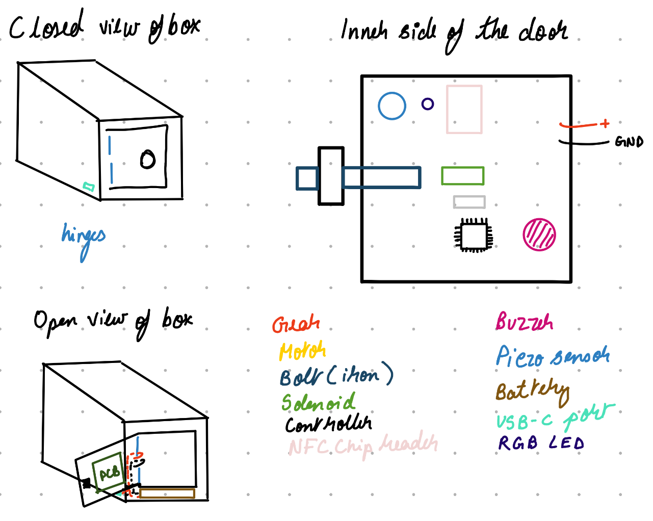
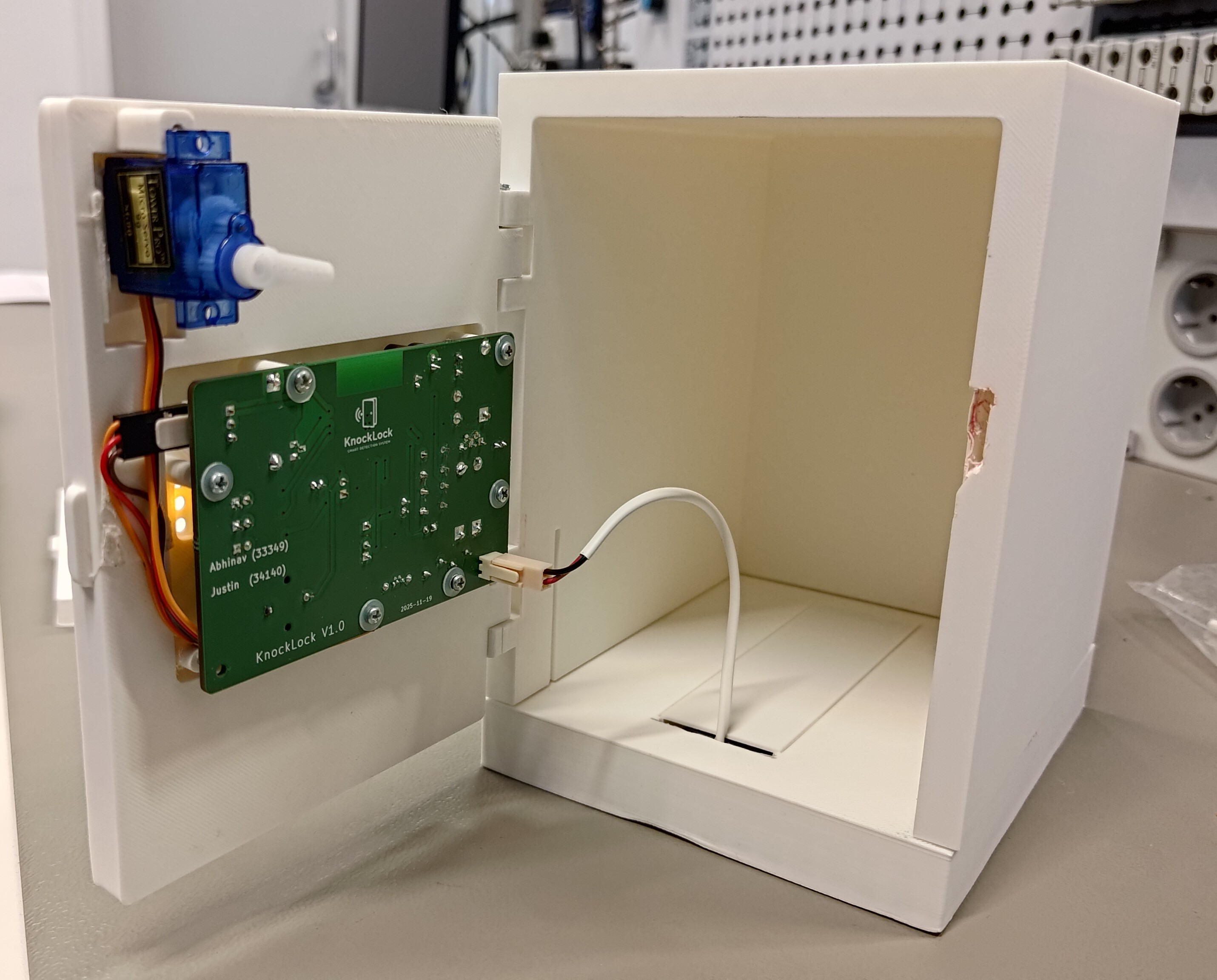
“First Concept Sketch and Final Product Side-by-Side”
This project was done as part of the course 2314 Practical Electronics at HSRW. It was completed alongside Abhinav Kothari. I did the schematic design of the motor control, programming interface and power protection as well as most of the PCB design and system verification. He did the design of the sensor circuit, HMI power regulation as well as software development, housing design and breadboard prototyping. The full project report can be found here.
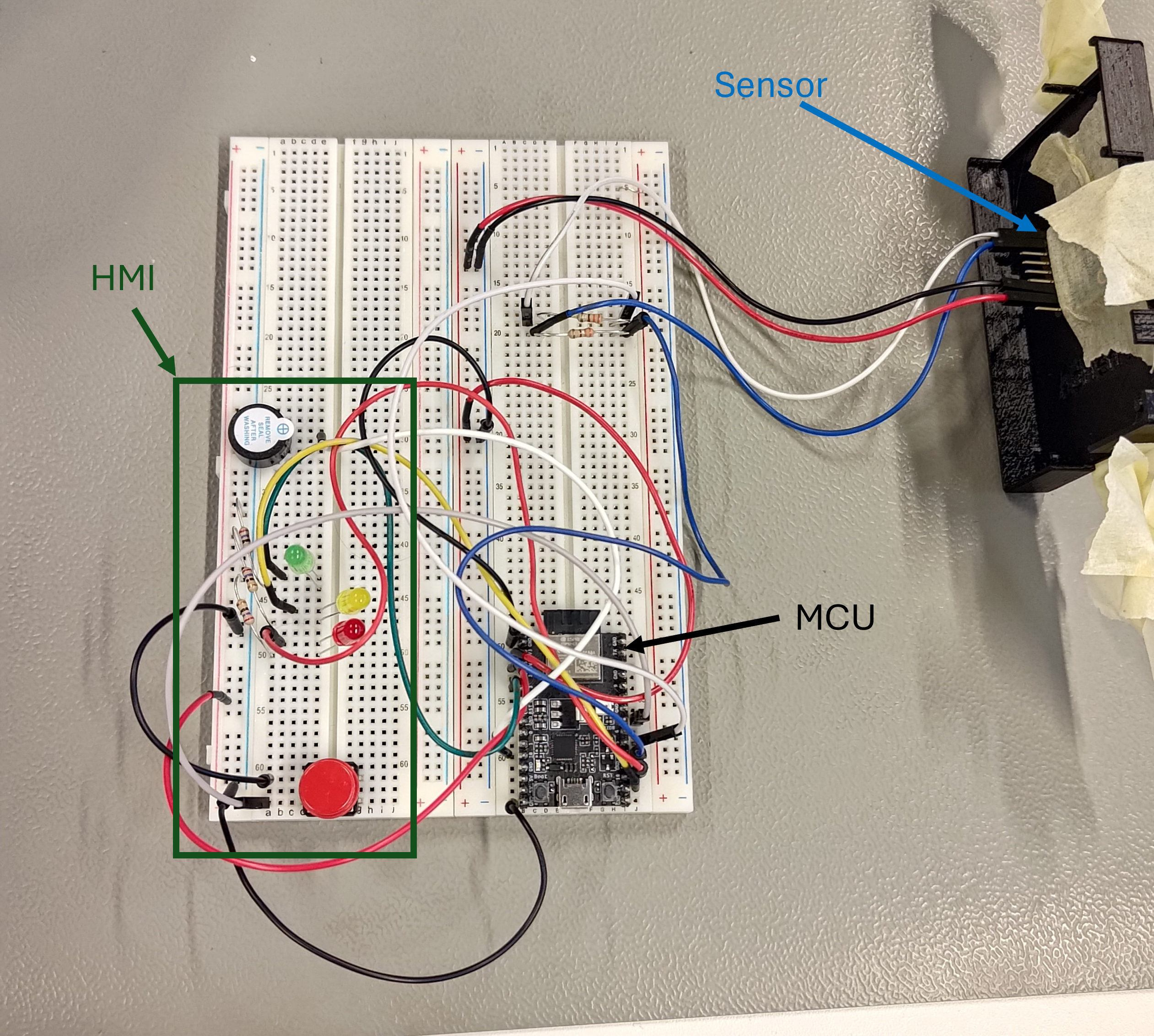
“System Prototype”
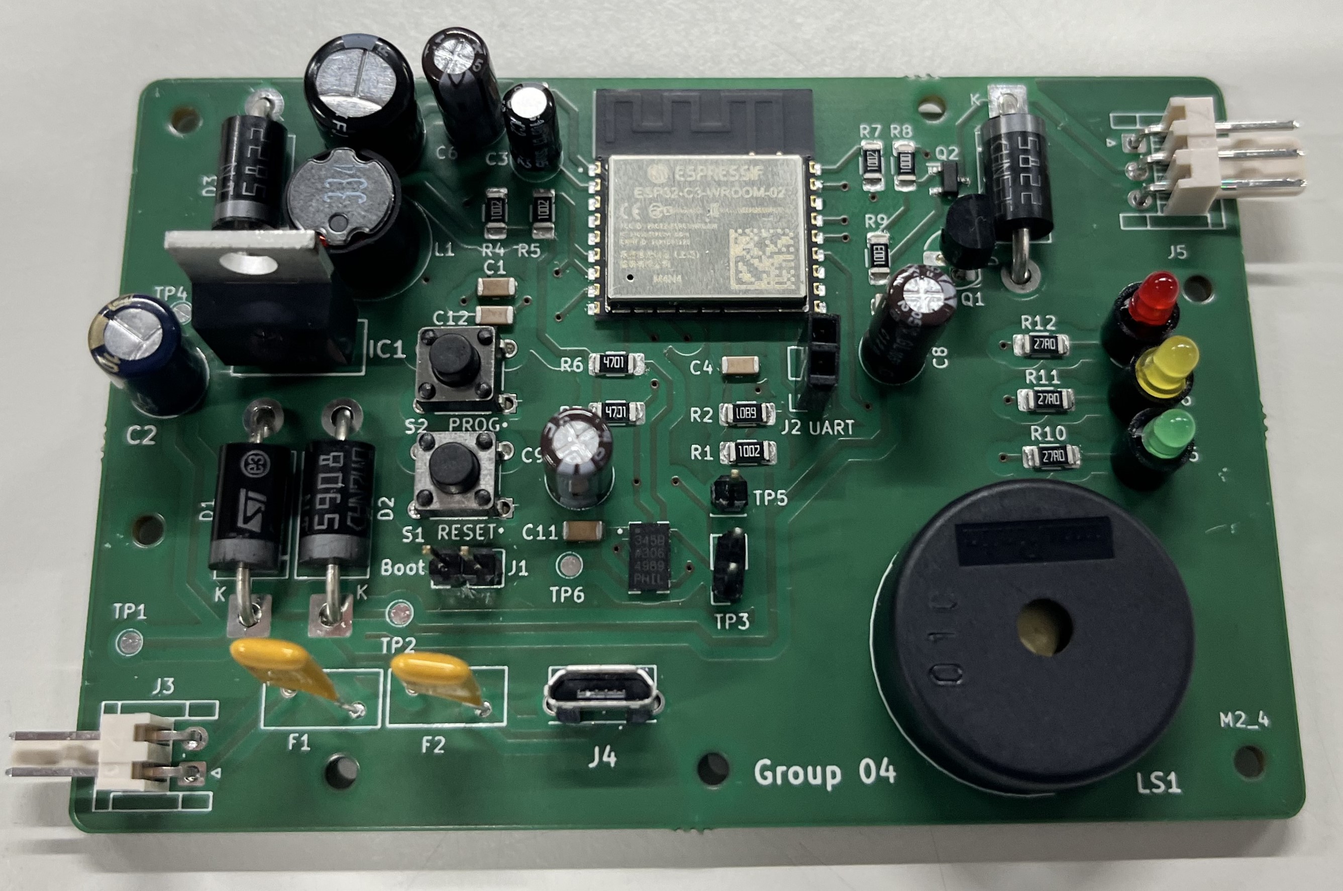
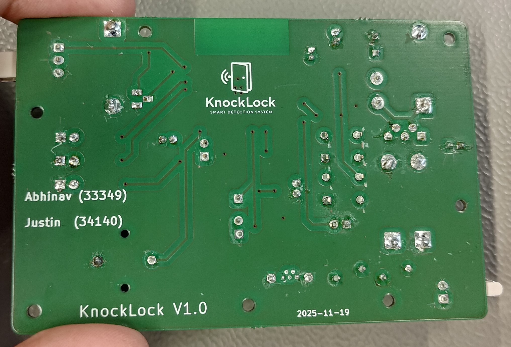
“PCB”
“Video Show Case”
🔧 Current Features
- Can reliably detect knocks and recognise knock patterns using an accelerometer to unlock the box
- Can lock and unlock the box using a servo motor
- Can be re-programmed to have any knocking pattern
- Alerts user when battery is low
- Goes into deep sleep to save battery when not in use
📦 Requirements
- Arduino IDE
For required hardware, see these bills of materials taken from the project report:
| Item | Schematic Ref | Qty | Component | Part Number | Manufacturer | Vendor | Price/Unit[€] | Price [€] |
|---|---|---|---|---|---|---|---|---|
| 1 | U1 | 1 | Capacitive Accelerometer | ADXL345BCCZ-RL7 | Analog Devices | Mouser | 5.65 | 5.65 |
| 2 | – | 1 | Servo Motor | SG90 | Soldered | HSRW | 5.07 | 5.07 |
| 3 | Q1 | 1 | Bipolar NPN Transistor | BC547B | CDIL | HSRW | 0.04 | 0.04 |
| 4 | Q2 | 1 | P-channel MOSFET | IRLML6402TRPBF | Infineon Technologies | Mouser | 0.35 | 0.35 |
| 5 | IC2 | 1 | ESP32 Microcontroller | ESP32-C3-WROOM-02-N4 | Espressif Systems | Mouser | 3.12 | 3.12 |
| 6 | D5 | 1 | Red LED | DLE3MMR | Hottech | HSRW | 0.06 | 0.06 |
| 7 | D6 | 1 | Yellow LED | DLE3MMY | Hottech | HSRW | 0.06 | 0.06 |
| 8 | D7 | 1 | Green LED | DLE3MMG | Hottech | HSRW | 0.06 | 0.06 |
| 9 | LS1 | 1 | Buzzer | PKM22EPPH4001-B0 | Murata Electronics | Mouser | 0.48 | 0.48 |
| 10 | S1, S2 | 2 | Push Button | TS02-66-60-BK-260-LCR-D | Samesky | Mouser | 0.09 | 0.18 |
| 11 | IC1 | 1 | 3.3 V Voltage Regulator | LM2575-3.3WT | Microchip Technology | Mouser | 1.48 | 1.48 |
| 12 | D1, D2 | 2 | TVS Diode | 1N5908 | STMicroelectronics | HSRW | 0.66 | 1.32 |
| 13 | D3, D4 | 2 | Schottky Diode | 1N5822 | MIC Electronics | HSRW | 0.15 | 0.30 |
| 14 | F1, F2 | 2 | Resettable Fuse | PFRA110 | Schurter | HSRW | 0.28 | 0.56 |
| 15 | – | 1 | Battery Holder | 2477 | Keystone Electronics | Mouser | 1.87 | 1.87 |
| 16 | – | 4 | AA Battery | – | – | HSRW | 0.30 | 1.20 |
| 17 | L1 | 1 | 330 µH Inductor | RFC0810B-334KE | Coilcraft | Mouser | 1.26 | 1.26 |
| 18 | C1, C4, C5, C10, C11, C12 | 6 | 0.1 µF Ceramic Capacitor (0805) | B37873U5101S | EPCOS | HSRW | 0.11 | 0.66 |
| 19 | C2 | 1 | 100 µF Electrolytic Capacitor | EEU-FC1C101H | Panasonic | HSRW | 0.14 | 0.14 |
| 20 | C3 | 1 | 1 µF Electrolytic Capacitor | RA1/25-R | Jameco | HSRW | 0.02 | 0.02 |
| 21 | C6, C8, C9 | 3 | 10 µF Electrolytic Capacitor | EEU-FR1H100 | Panasonic | HSRW | 0.11 | 0.33 |
| 22 | C7 | 1 | 330 µF Electrolytic Capacitor | EEU-FR1E331 | Panasonic | HSRW | 0.26 | 0.26 |
| 23 | J1 | 1 | Male 2-Pin Header | – | – | HSRW | 0.08 | 0.08 |
| 24 | J2 | 1 | Female 2-Pin Header | – | – | HSRW | 0.10 | 0.10 |
| 25 | J3 | 1 | Male JST 2-Pin Header | – | – | HSRW | 0.10 | 0.10 |
| 26 | J4 | 1 | Micro USB B | USB3145-30-1-A | GCT | Mouser | 0.66 | 0.66 |
| 27 | J5 | 1 | Male JST 3-Pin Header | – | – | HSRW | 0.12 | 0.12 |
| 28 | R1, R4, R5, R7 | 4 | 10 kΩ Resistor | RC1206FR-0710KL | YAGEO | HSRW | 0.09 | 0.36 |
| 29 | R2 | 1 | 6.8 kΩ Resistor | RC1206FR-076K8L | YAGEO | HSRW | 0.09 | 0.09 |
| 30 | R3, R6 | 2 | 4.7 kΩ Resistor | RC1206FR-074K7L | YAGEO | HSRW | 0.09 | 0.18 |
| 31 | R8 | 1 | 100 Ω Resistor | RC1206FR-07100RL | YAGEO | HSRW | 0.09 | 0.09 |
| 32 | R9 | 1 | 100 kΩ Resistor | RC1206FR-07100KL | YAGEO | HSRW | 0.09 | 0.09 |
| 33 | R10, R11, R12 | 3 | 27 Ω Resistor | RC1206FR-0727RL | YAGEO | HSRW | 0.09 | 0.27 |
| Total | 26.61 |
| Item Number | Qty | Component | Price / Unit | Price |
|---|---|---|---|---|
| 35 | 7 | M2×6 Screw | 0.11 | 0.77 |
| 36 | 2 | M2×20 Screw | 0.14 | 0.28 |
| 37 | 1 | M3×15 Plastic Screw | 0.08 | 0.08 |
| 38 | 7 | M3 Plastic Washer | 0.01 | 0.07 |
| 39 | 1 | M3 Hex Nut | 0.07 | 0.07 |
| 40 | 1 | 3D Printed Housing | 8.43 | 8.43 |
| Total | 9.70 |
🚧 Future Work
- Rechargeability: Implementing a recharging circuit on the existing micro USB-B port and using rechargable batteries
- Redundant sensors: Use Piezo with ADXL to more effectively detect a knock
- Improved Ergonomics: Using a material that does not hurt to knock, a housing shape which does not hurt to carry around and also does not slide when knocked on
- Better locking mechanism: Using a solenoid to lock the system to make it more secure
- Recovery: Possible recovery method for pattern in case forgotten
- Multiple passwords: Possibility to store multiple passwords
- Alternative entry: An alternative entry mechanism, perhaps mechanical
📚 References
Analog Devices. ADXL345 [Datasheet]. Analog Devices.
Espressif Systems. ESP32-C3 Series [Datasheet]. In Espressif, 2021
GAMMON, Nick. High side driver. Gammon.com, 2015.
SCHERZ, Paul. Practical Electronics for Inventors. Mc Graw Hill, 2016.