Chassis Assembly
I attached the motors to the chassis and tested the directions of travel.
Then I soldered some wires to the leads of the motors for easier access.
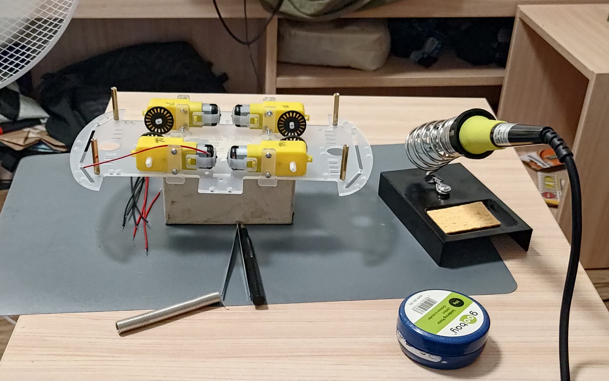
I am using four 1.5V batteries (6V) as a power supply for the motors.
Motor Control System
After the motors where all attached and moving the correct direcion, I wired the L298 motor drivers along with the Arduino.
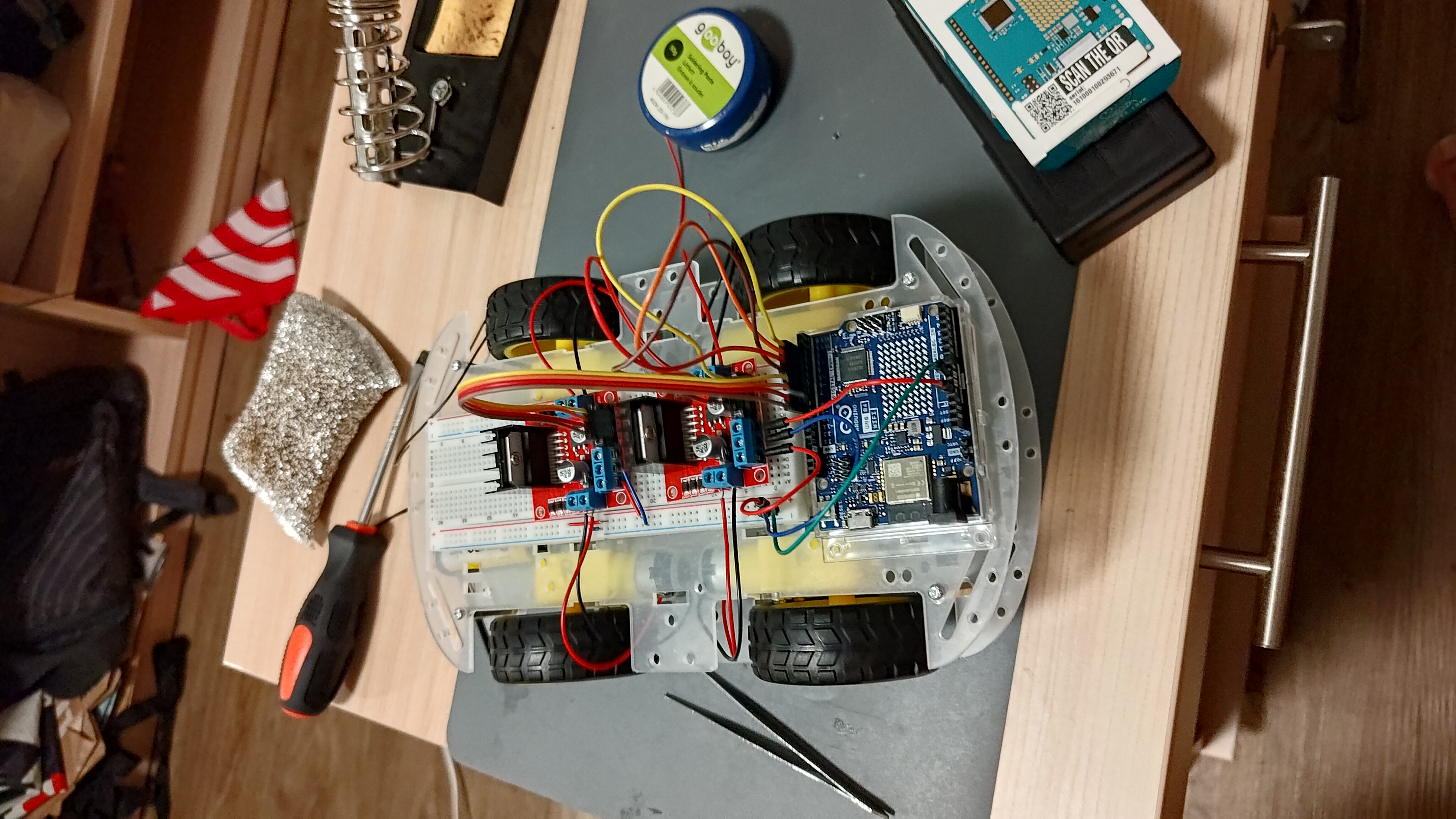
To test the first driver, I create a simple script to drive in forward then stop and then reverse
// ***************** PINS **********************
// Front Right Motor (FR)
int motorFRpin1 = 5;
int motorFRpin2 = 4;

// Front Left Motor (FL)
int motorFLpin1 = 3;
int motorFLpin2 = 2;
// ********************************************

void setup() {
  // Set all motor pins to output
  pinMode(motorFRpin1,OUTPUT);
  pinMode(motorFRpin2,OUTPUT);
  pinMode(motorFLpin1,OUTPUT);
  pinMode(motorFLpin2,OUTPUT);

}

void loop() {
  // Forward for 2 seconds
  digitalWrite(motorFRpin1, HIGH);
  digitalWrite(motorFRpin2, LOW);

  digitalWrite(motorFLpin1, HIGH);
  digitalWrite(motorFLpin2, LOW);
  delay(2000);

  // Stop for 1 sec
  digitalWrite(motorFRpin1, LOW);
  digitalWrite(motorFRpin2, LOW);

  digitalWrite(motorFLpin1, LOW);
  digitalWrite(motorFLpin2, LOW);
  delay(1000);

  // Reverse for 2 secs
  digitalWrite(motorFRpin1, LOW);
  digitalWrite(motorFRpin2, HIGH);

  digitalWrite(motorFLpin1, LOW);
  digitalWrite(motorFLpin2, HIGH);
  delay(2000);

}
When I was wiring the first motor driver and tested it with some simple Arduino code, I noticed the motors seem to pause on each loop
I suspect this is due to single 6V supply being insufficient for the Arduino, the motors and L298. This is why I added an extra 9V cell to supply the Arduino.
Ultrasonic Sensor
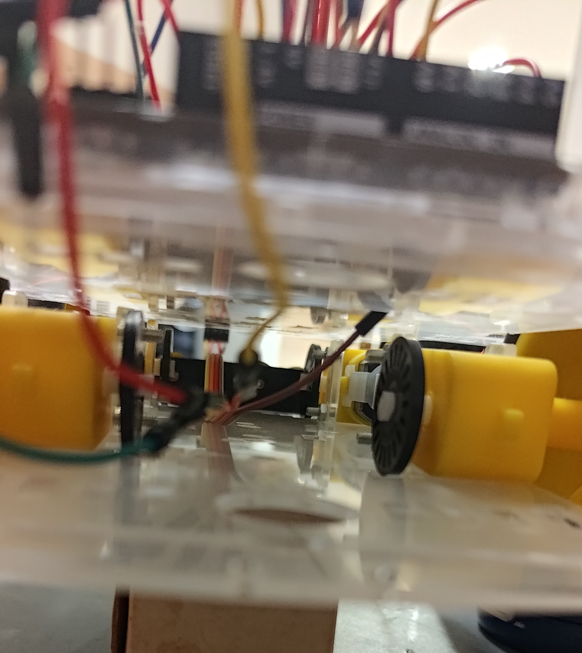
To mount the ultrasonic sensor, I couldn’t just pin it into the breadboard as that would just connect all of the pins together due to the orientation of the breadboard. So I decided to use male to female jumpers which I then ran through the chassis of the car towards the Arduino. This made me have to change the direction of travel, so I had to switch the pins in the Arduino code for the motors drivers.
I also made some adjustments to the code.
Added pins for the trigger and echo of the sensor
// Ultrasonic Sensor
#define Trigger 12
#define Echo 13
initial setup for correct i/o config
// Set Echo and Trigger for US Sensor
  pinMode(Echo, INPUT);
  pinMode(Trigger, OUTPUT);
added pulse and reading to the loop, plus I calculated distance and created a simple emergency stop logic
void loop() {
  // Set Trigger LOW
  digitalWrite(Trigger, LOW);
  delayMicroseconds(2);

  // Emit high frequency 40kHz sound pulse (i.e. pull the Trigger)
  digitalWrite(Trigger, HIGH);
  delayMicroseconds(10);
  digitalWrite(Trigger, LOW);

  // Detect a pulse
  int distance = pulseIn(Echo, HIGH);

  // Speed of sound is: 343 m/s -> 343 x 10^2 cm/s -> 343 x 10^2 x 10^-6 cm/us -> 29.15451895 us/cm
  distance = distance / 29 / 2;  // in cm
  // we divide by 2 to acount for the round trip

  // Driving Logic
  if (distance <= 10){
    // Emergency stop
    digitalWrite(FR_f, LOW);
    digitalWrite(FR_r, LOW);
    digitalWrite(FL_f, LOW);
    digitalWrite(FL_r, LOW);
    digitalWrite(RR_f, LOW);
    digitalWrite(RR_r, LOW);
    digitalWrite(RL_f, LOW);
    digitalWrite(RL_r, LOW);
  } else {
    // Forward Drive
    digitalWrite(FR_f, HIGH);
    digitalWrite(FR_r, LOW);
    digitalWrite(FL_f, HIGH);
    digitalWrite(FL_r, LOW);
    digitalWrite(RR_f, HIGH);
    digitalWrite(RR_r, LOW);
    digitalWrite(RL_f, HIGH);
    digitalWrite(RL_r, LOW);
  }
  // Print the distance in inches
  Serial.println(distance);

  // Pause for 100 milliseconds
  delay(200);
}
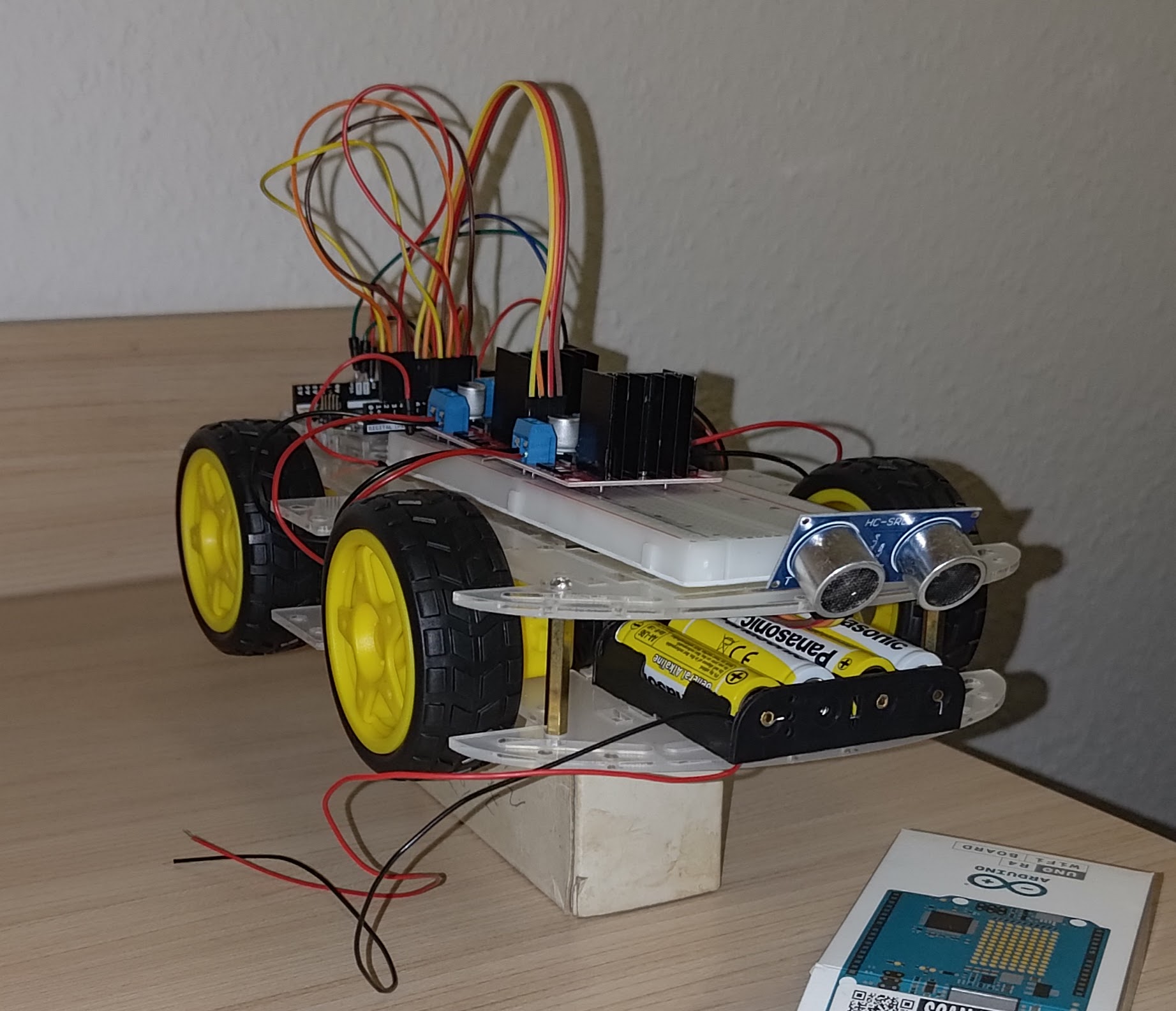
Final Result
Finally, I had a basic car that moves foward until it detects an obstacle within 10cm of the sensor.
Pin Connections
| Arduino/Breadboard | Component | Comment |
|---|---|---|
| 7 | Front L298N IN1 | Forward for Front Right Motor |
| 6 | Front L298N IN2 | Reverse for Front Right Motor |
| 9 | Front L298N IN3 | Forward for Front Left Motor |
| 8 | Front L298N IN4 | Reverse for Front Left Motor |
| 2 | Rear L298N IN1 | Forward for Rear Right Motor |
| 3 | Rear L298N IN2 | Reverse for Rear Right Motor |
| 4 | Rear L298N IN3 | Forward for Rear Left Motor |
| 5 | Rear L298N IN4 | Reverse for Rear Left Motor |
| GND | Both L298N GND, Ultrasonic Sensor GND | Must GND L298N, Arduino, and power supply |
| 5V | Rear L298N 5V | To power Arduino or vice-versa |
| Left Power Rail + | Front L298N 5V, Ultrasonic Sensor PWR | L298N outputs the 5V which powers the US sensor |
| Right Power Rail + | Both L298N 12V | To power the motor drivers |
| 12 | Ultrasonic Sensor Trigger | Input to send pulse |
| 13 | Ultrasonic Sensor Echo | Output of time for reception |